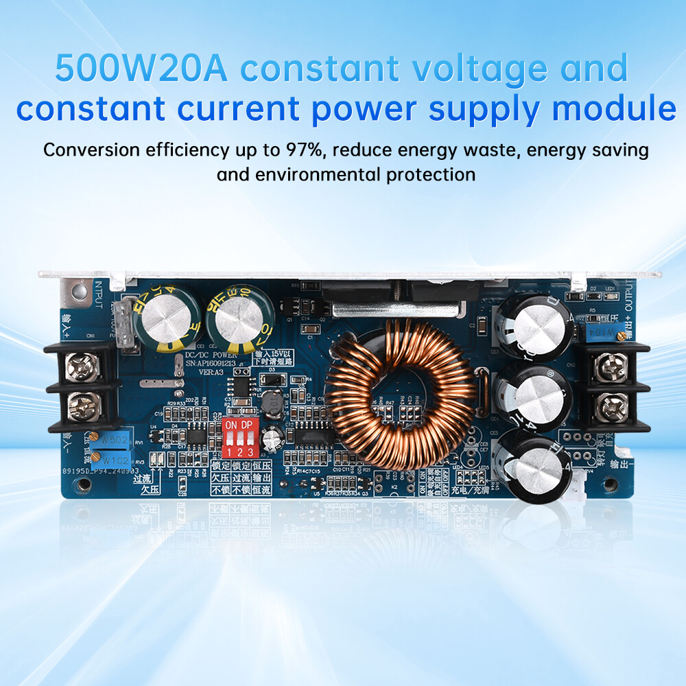
Product Feature:
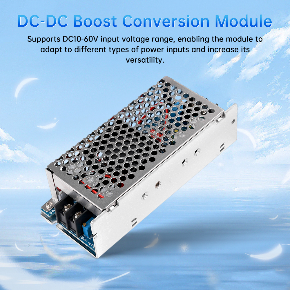
1. Supports an input voltage range of DC10-60V, enabling the module to adapt to different types of power inputs and increase its versatility
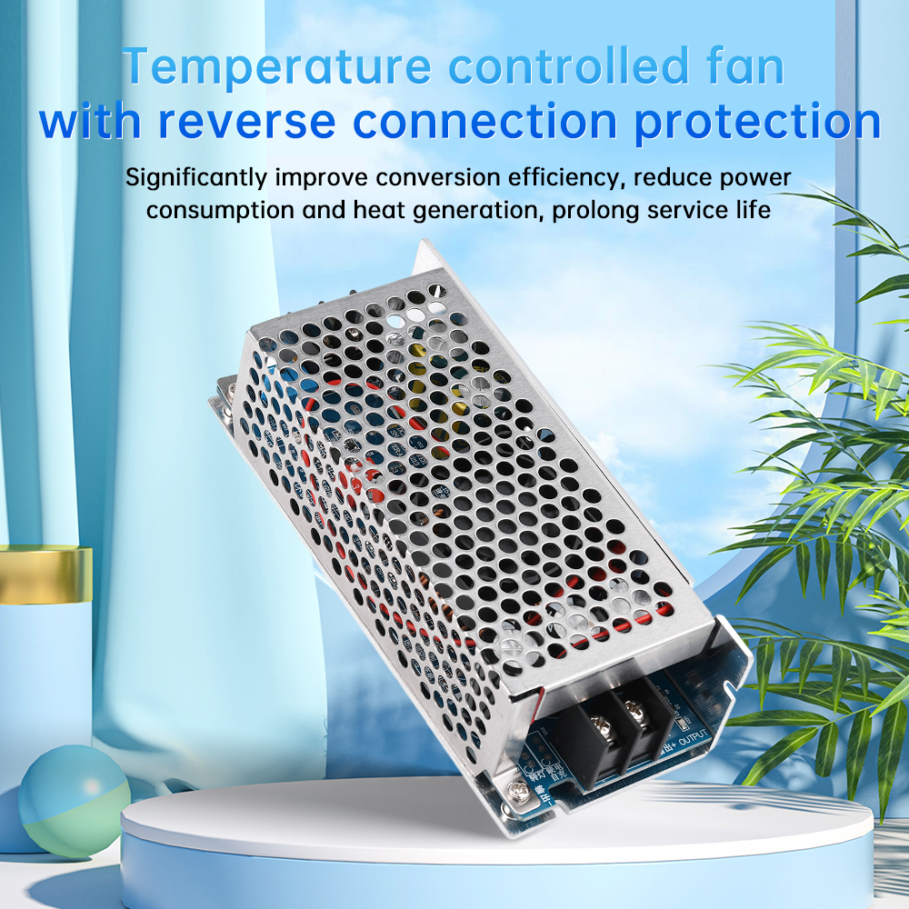
2. Significantly improve conversion efficiency, reduce power consumption and heat generation, and extend service life
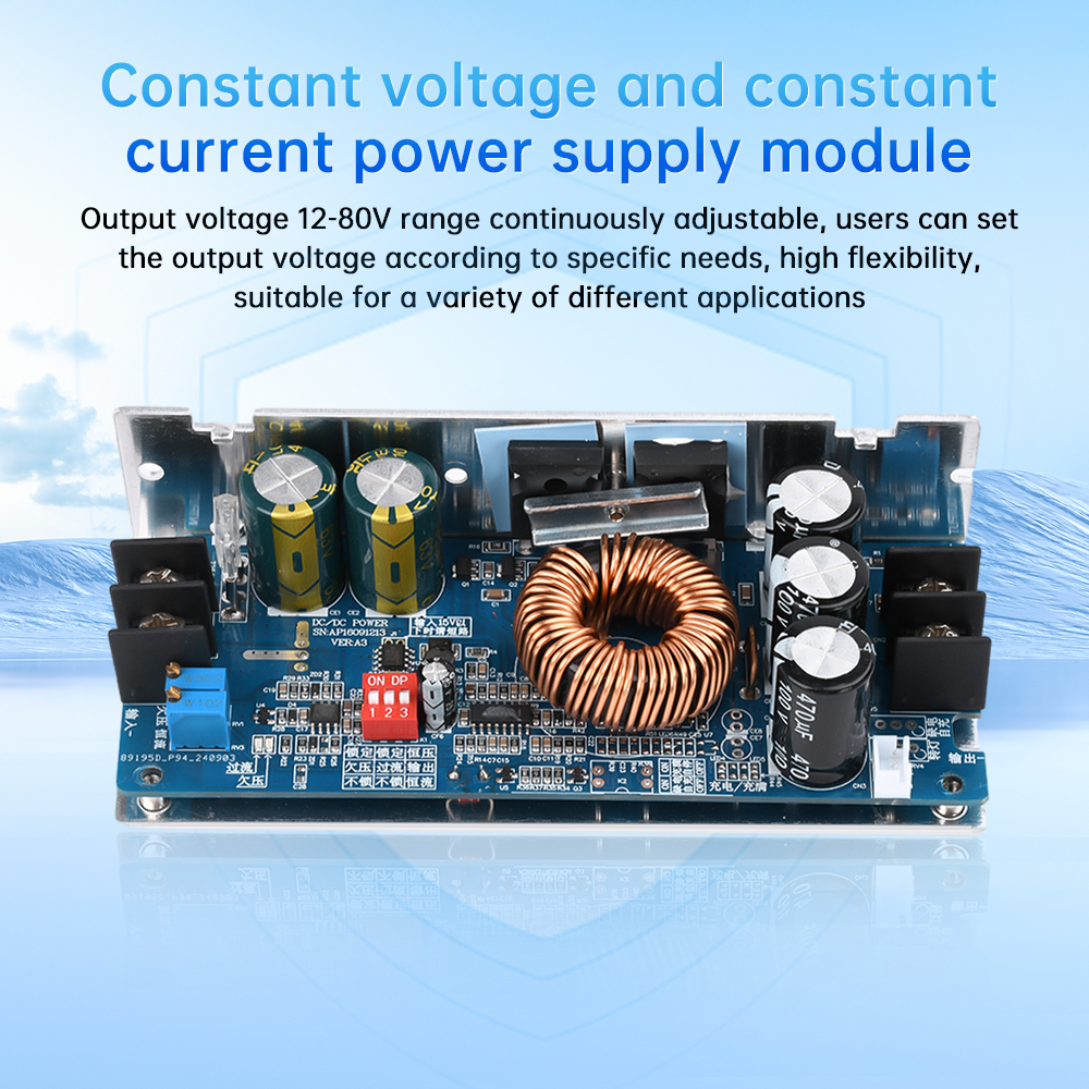
3. The output voltage can be continuously adjusted within the range of 12-80V, and users can set the output voltage according to their specific needs. It has high flexibility and is suitable for various application scenarios
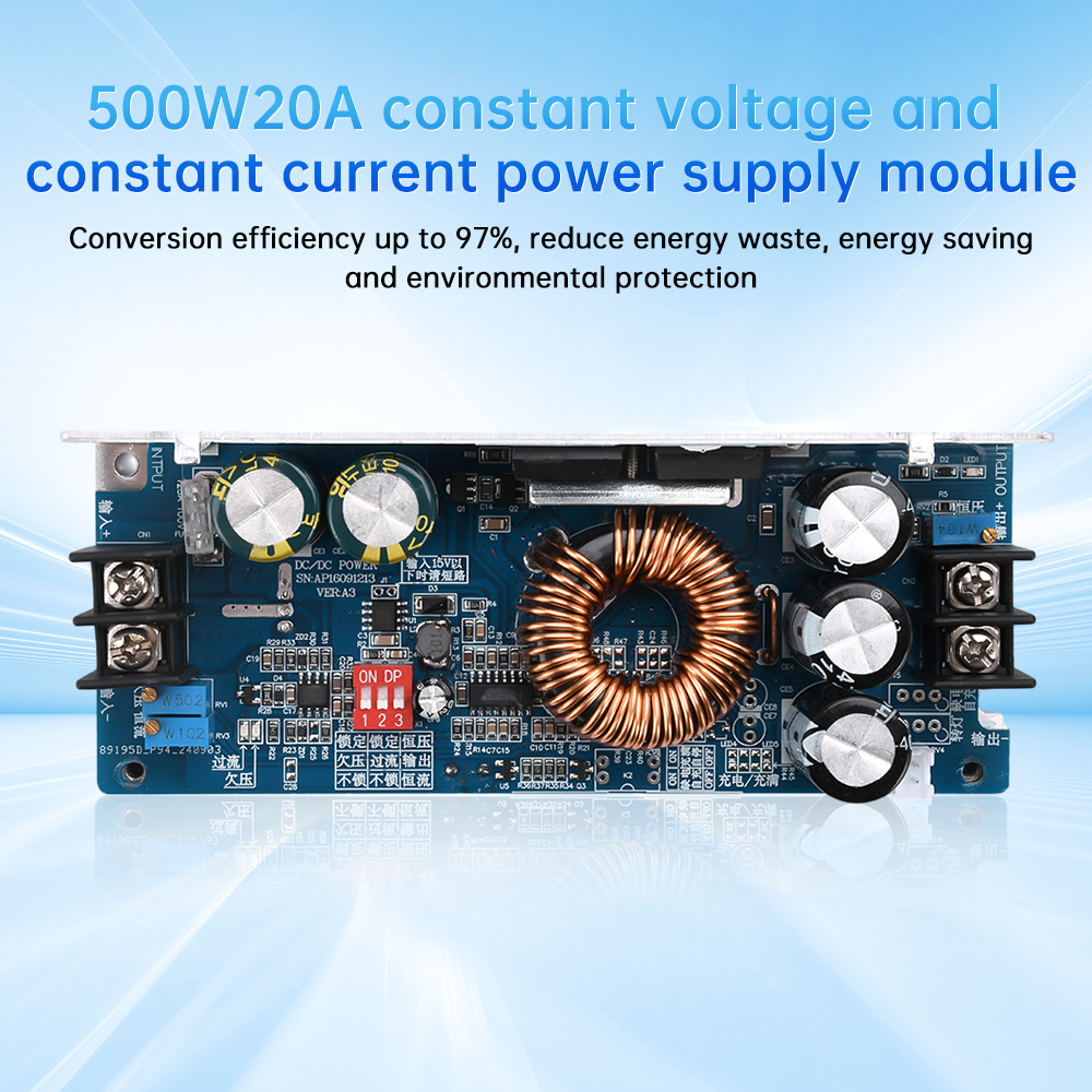
4. The conversion efficiency can reach 97%, reducing energy waste and promoting energy conservation and environmental protection
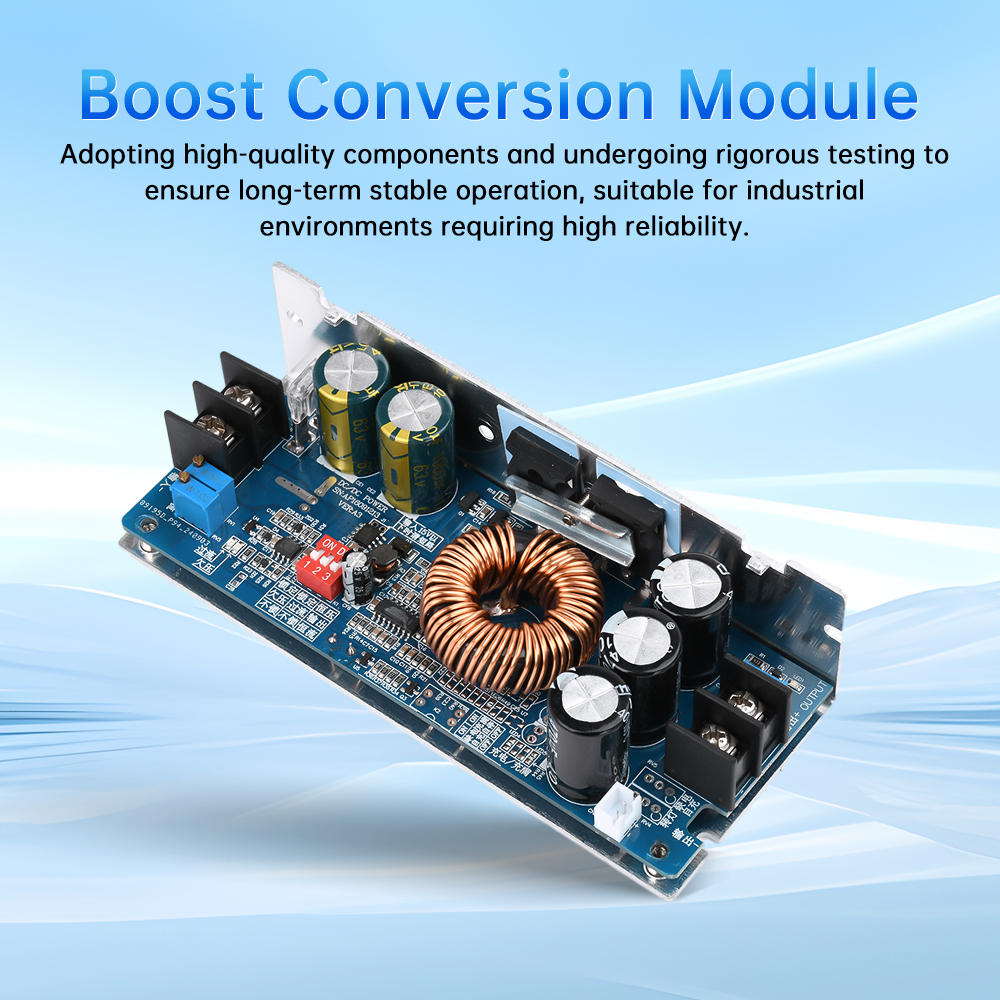
5. Using high-quality components, rigorously tested to ensure long-term stable operation, suitable for industrial environments that require high reliability
Product parameters:
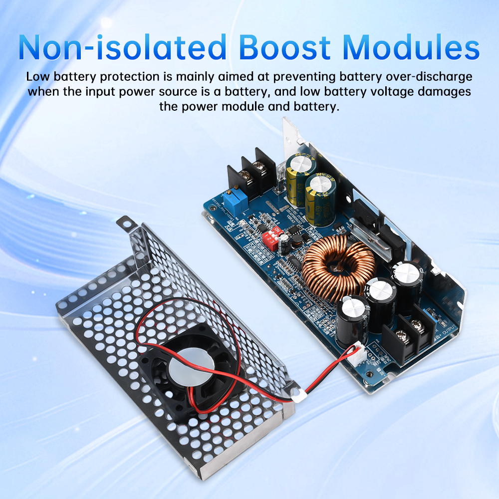
Module nature: Non isolated boost module (BOOST)
Input voltage: DC10.5-60V
Input current: 20A MAX (input current calculation formula: output power/input voltage * 1.05=input current)
Output voltage: 12-80V adjustable (output voltage can only be higher than input voltage)
Static working current: 15mA (When the output voltage increases from 12V to 20V, the static current will increase as the output voltage increases)
Output current: 15A MAX
Constant current range: 0.5-15A (+/-0.5A)
Input anti reverse connection: Yes (150A power MOS anti reverse)
Low battery protection: available (adjustable from 10-45V)
Temperature controlled fan: Yes (turns on the fan when the temperature exceeds 55 degrees)
Working temperature: -40~+85 degrees (please strengthen heat dissipation when the ambient temperature is too high)
Working frequency: 100KHz
Conversion efficiency: 92% -97% (efficiency is related to input and output voltage, current, and voltage difference. Low voltage difference results in high efficiency)
Input overcurrent protection: Yes (if the input exceeds 22A, the output power will be reduced)
Short circuit protection: None (prohibit short circuit output)
Input reverse protection: Yes (150A power MOS transistor anti reverse. Can be reversed for a long time)
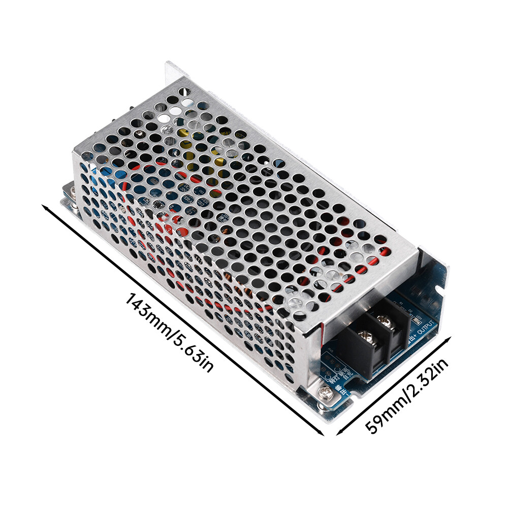
Wiring method: Wiring terminal (please use high current pure copper wire)
Output power description:
Output power=Input voltage * 20A, for example: Input voltage 12V, 12V * 20A=240W. The maximum power at 12V input is 240W
For example, when 24V * 20A=480W is input, the maximum power is 480W when 24V is input,
For example: Input 36V, 36V * 20A. At this time, the power is 720W, which exceeds the power of the power supply. At this time, the input current cannot exceed 13.8A
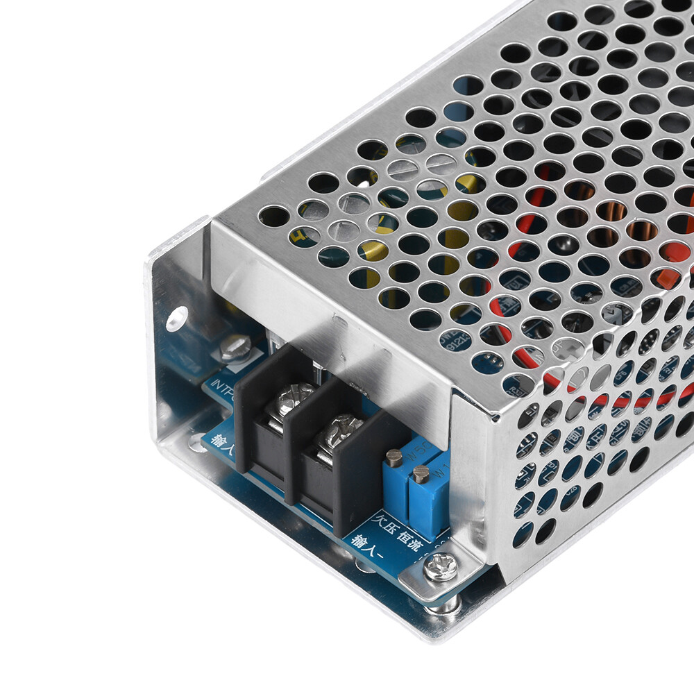
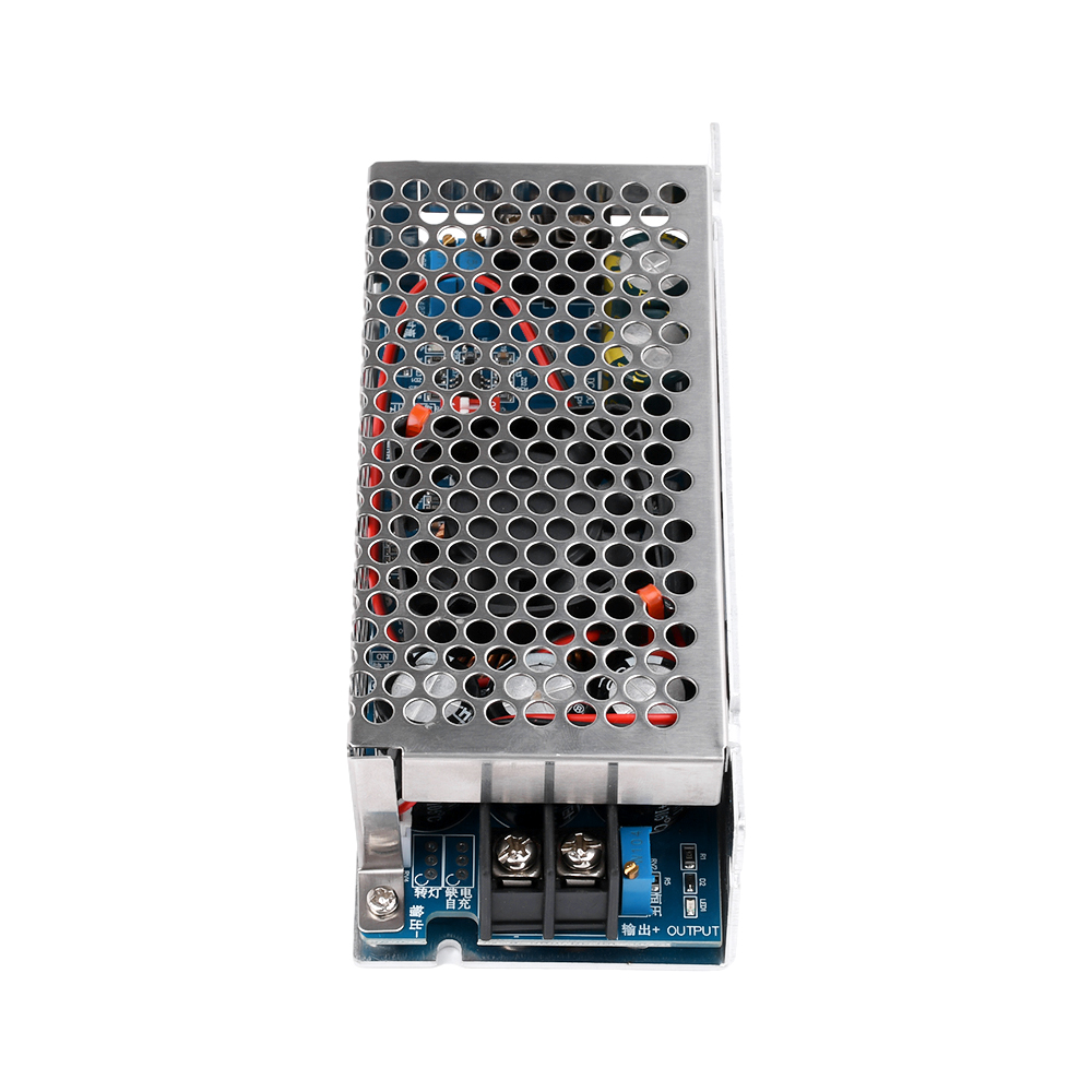
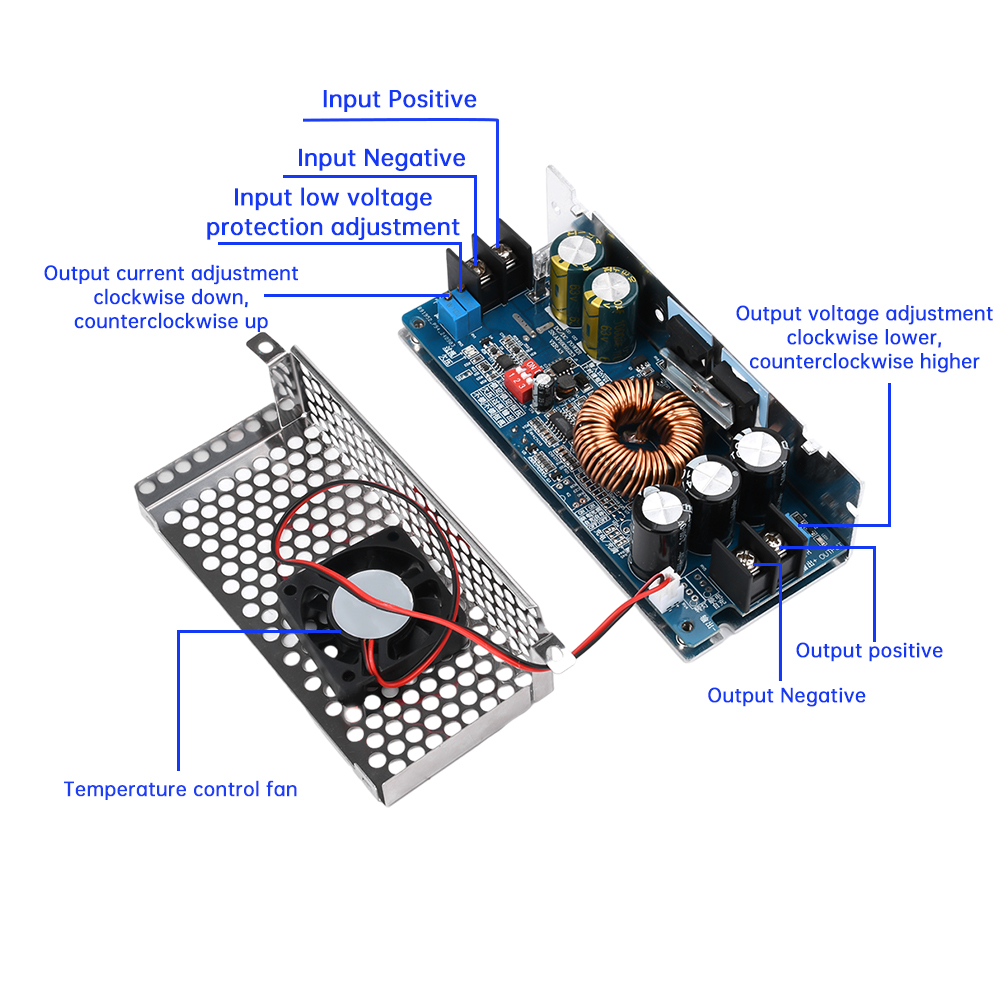
Output voltage/output current regulation/input low battery protection regulation
Voltage regulation: When the power is turned on and there is no load, use a flathead screwdriver to adjust the output terminal "RV2" potentiometer (indicated in the figure below) clockwise to lower and counterclockwise to increase. Due to the large capacity of the output capacitor, the response time when adjusting the output voltage from high voltage to low voltage will be relatively slow. The amplitude of the instrument adjustment is smaller.
Current regulation: Turn the "RV3" potentiometer clockwise for about 30 turns, set the output current to the minimum, connect the LED or battery, and turn the "RV3" potentiometer counterclockwise to the desired current. For battery charging, after the battery is discharged, it is connected to the output and adjusted to the current you need. When charging, it must be adjusted after the battery is discharged base note. (Do not adjust the current by short circuit output. The circuit structure of the boost module cannot be adjusted by short circuit,
Input low battery protection regulation: Low battery protection is mainly aimed at preventing battery overdischarge and damage to the power module and battery caused by low battery voltage when the input power source is a battery. For example, setting low battery protection for 12V batteries. Connect a 10V voltage to the input terminal of the power module and use a Phillips screwdriver to adjust RV1 (clockwise to increase the voltage value of the protection point, counterclockwise to decrease the voltage value of the protection point) until the "undervoltage" indicator light is on. At this time, the low battery protection voltage is 10V. When the battery voltage drops to 10V, the power module does not rise (the input voltage is equal to the output voltage)
matters needing attention:
1. This power supply is a boost power supply, which can only boost and cannot be used for voltage reduction. The output voltage can only be higher than the input voltage. When the input voltage is higher than the set output voltage, the output voltage is as high as the input voltage.
When used for constant current charging, it is necessary to ensure sufficient input and output voltage difference. For example, when inputting 12V, only batteries above 24V can be charged, and batteries below 12V cannot be charged. If the input power is 24V, only batteries above 36V can be charged, and batteries below 36V cannot be charged.
3. The input current should not exceed 20A during use. (Input current calculation formula: Output power/Input voltage * 1.05=Input current. For example, if the input is 12V, the output is 36V, and the output is 8A, the input current=(36V * 10A/12V) 1.05=Input current 31.5A. This has exceeded 20A and is not allowed.)
4. Strengthen heat dissipation when working at full load for a long time
5. The input power cannot exceed 500W (power: input voltage * input current)
6. It is strictly prohibited to short-circuit output and adjust current
When selecting a power supply, the power of the power supply should be more than 1.5 times the load power
Package List:
500W boost power module * 1