

We stand behind every product we sell.
All of our brand new items come with a 30-Day money-back or exchange guarantee.


|
|
|

|

|

|

|

|

|

|

|

|

|

|

|

|

|
Kit Part Includes
Quantity
Fits
Specifications
NOTES
2.Package Includes:
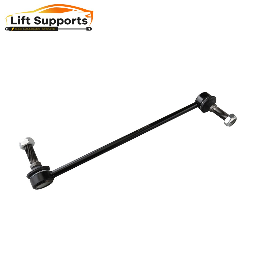
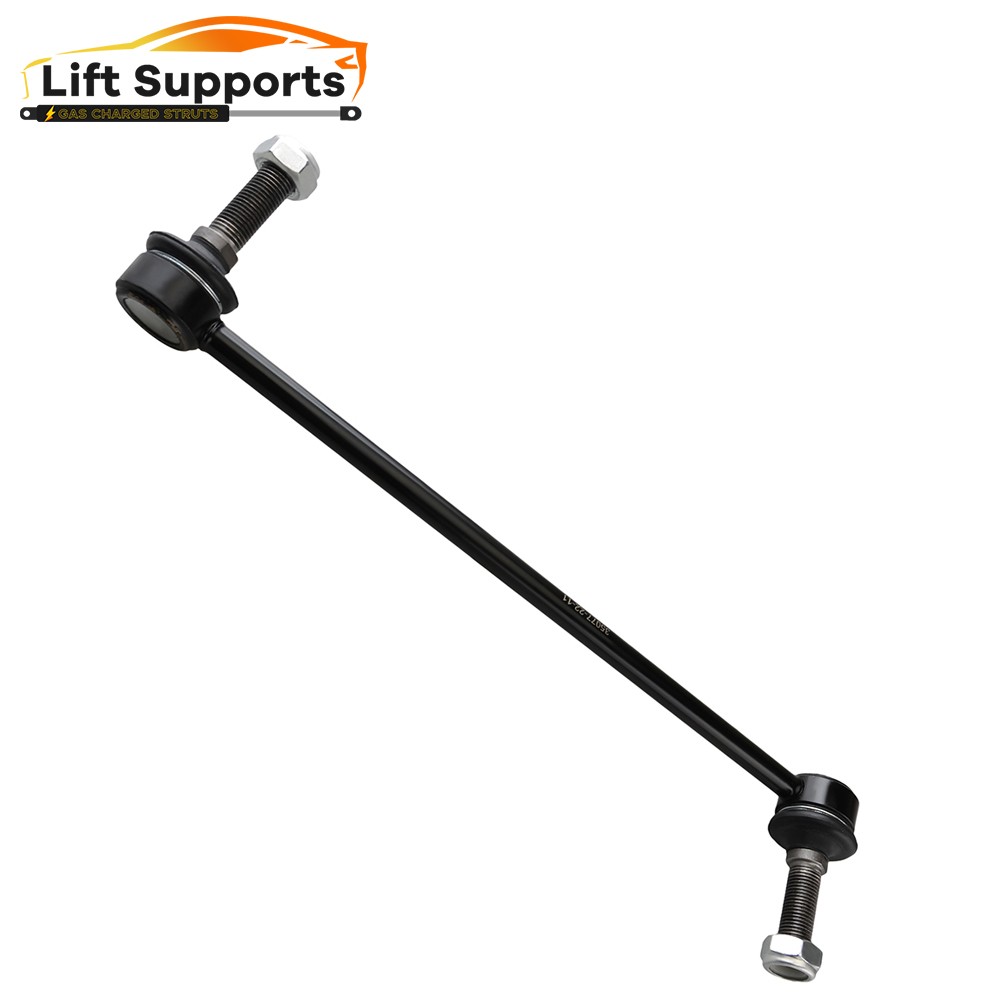
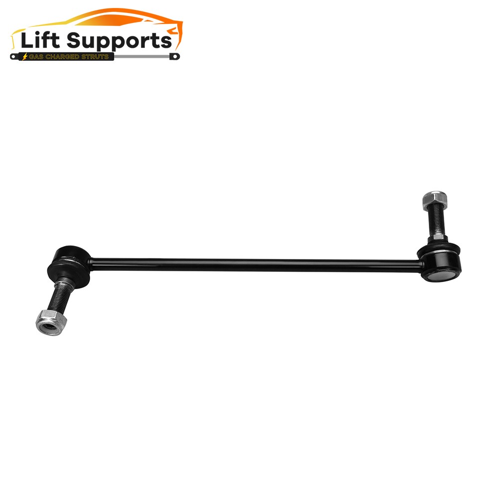
2 x Part# Front Outer Tie Rod End Link - ES80805
3.Note
Although some parts have grease fittings, other parts are factory sealed, but do not affect the fit and quality of the parts.
Please check above compatibility list to make sure it fits your vehicle.
If you want to find more about suspension kits,clicking our store.
Tie-Rod End
The tie-rod assemblies connect the center link to the steering arms, which are bolted to the front steering knuckles. In some front suspensions, the steering arms are part of the steering knuckle; in other front suspension systems, the steering arms are bolted to the knuckle. A ball socket is mounted on the inner end to each tie-rod, and a tapered stud on this socket is mounted in a center link opening. A castellated nut and cotter pin retain the tie-rods to the center link. A threaded sleeve is mounted on the outer end of each tie-rod, and a tie-rod end is threaded into the outer end of this sleeve.

Outer Tie-Rod End
Some outer tie-rod ends have a ball stud that is surrounded by an upper hardened steel bearing and a high-strength polymer lower bearing seat. The hardened steel upper bearing provides strength and durability, and the polymer lower bearing seat provides smooth rotation of the ball stud in the tie-rod end. An internal spring between the polymer lower bearing seat supplies self-adjusting action and constant tension on this seat. A seal in the upper part of the ball joint housing seals the ball stud to prevent contaminants from entering the tie-rod end. These tie-rod ends are installed on some original equipment manufacturer’s vehicles, and they are available as replacement tie-rod ends on most vehicles.

Inner Tie-Rod End
Some inner tie-rod ends contain a bolt and bushing. These tie-rod ends are threaded onto the rack. Since the rack is connected directly to the tie-rods, the rack replaces the center link in a parallelogram steering linkage.
Some inner tie-rod ends have a mirror-finished ball and a high-strength polymer bearing to ensure low torque, minimal friction, and extended life. A hardened alloy steel rod extends from the ball to the outer tie-rod end and provides maximum strength and durability.
Tie-Rod End Replacement Guideline:
If you feel a bump in the steering when driving over road bumps or curbs, this might be due to worn tie rod ends or inner tie rods. Clicking noises during sudden steering movements can also be symptoms of a defective tie rod. In order to determine the exact cause and replace the defective tie rod, the car must be elevated with a vehicle lift in order to be examined more closely.
This useful tip applies to the exchange of tie rod ends and inner tie rods, which together form the so-called tie rod.


Picture(A)
Note: Cleanliness is extremely important when working on the power steering. Incorrect work and contamination can lead to leakage and, in the worst case, to failure of the steering assistance.
1.Lift the vehicle and dismount the front axle wheels.
2.Spray the fastening nut of the tie rod end with rust remover and leave it on for a few minutes.
Picture(B)
3.Dismount the front underride guard.


Picture(C)
4.Loosen the fastening nut from the tie rod and remove it completely.
5.Remove the tie rod end from the steeringknuckle using an appropriate ball joint separator.
Picture(D)
6.Remove the clamp of the bellow on the steering gear.
7.Push the bellow towards the tie rod end.


Picture(E)
8.Unscrew the inner tie rod from the rack.
9.Clean the sealing face of the bellow at the steering gear.
Picture(F)
10.Clean the lug of the rubber contact surface of the ball joint in the steering knuckle.
Note:Always use new self-locking nuts and bolts for a reliable repair.
11.Screw the new inner tie rod into the rack and tighten it with the tightening torque that has been specified by the vehicle manufacturer.


Picture(G)
12.Mount the bellow and close the clamps with the appropriate special tool.
Note:Incorrect mounting of the bellow can lead to corrosion of the rack: the steering gear starts leaking which can lead to a failure in the steering assistance.
Picture(H)
13.Secure the ball joint in the steering knuckle and mount the nut. Please observe the tightening torque suggested by the vehicle manufacturer.
Note:During mounting, the ball stud should not turn within the ball joint. This can cause damage inside the ball joint and can lead to early failure.
Tip:Secure the ball stud against twisting with a suitable tool.

Picture(I)
14.Mount the front underride guard.
15.Mount the front wheels and tighten them with the tightening torque recommended by the vehicle manufacturer.
16.Align the wheels and adjust them if necessary. Observe the vehicle manufacturer specifications.
17.Perform a test drive.
Note:When performing the test drive, pay special attention to the handling while cornering and listen for possible noise emission.
More of what you like


| Item Specifics | |
|---|---|
| Brand | Liftsupports |
| Manufacturer Part Number | L842426RTS |
| Manufacturer Warranty | 10 Year |
| Fitment Type | Direct Replacement |
| Placement on Vehicle | Front Left Right |
| Adjustable | No |
| Custom Bundle | Yes |
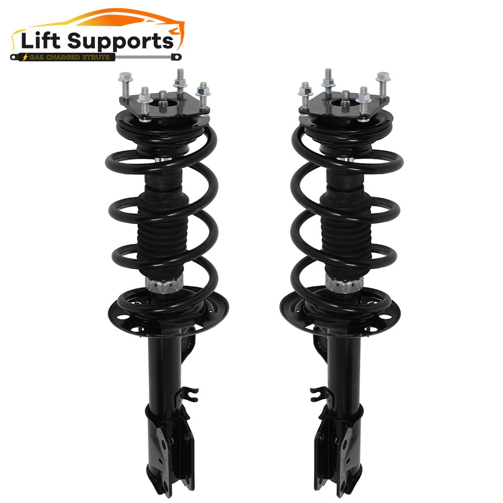
| Items Included | Complete Struts ,Sway Bar End Link ,Shock Absorber |
| Finish | Polished, Rust Protected |
| Included Hardware | Mounting Hardware |
| OE Spec or Performance/Custom | OE Spec |
| Type | Strut & Coil Spring Assembly |
| Features | Sealed |
| Modified Item | No |
| Gas Charged Shock | Yes |
| Interchange+Part+Number | 172621 172620 K750616 K750617 |
| Other Part Number | driver passenger side, coil spring upper mount shocks |
| Superseded Part Number | front strut assembly, stabilzer link, sway bar end links front |
1. If you want to change the shipping address, please contact us by eBay messages.
2.(if you want cancel orders or change address pls contact us within 6 hours after payment,or we are not responsible for shipping a replacement.)
3.Payment must be received within 10 days as auction ended or order might be delayed.
We stand behind every product we sell.
All of our brand new items come with a 30-Day money-back or exchange guarantee.
· We will leave a feedback once we get your payment.
· If you are dissatisfied for any reason, please do contact us a feedback. We will work hard to make sure EVERY CUSTOMER 100% SATISFIED and resolve any problem for you and always leave a feedback to all our customers.
· If you are satisfied with the product you received, wish you can leave us a feedback.
Hot Item
Best Seller
|
For Ford Explorer 2011-2013 w/ Coil Spring Assembly + Sway Bar Link Front Struts
Kit Part Includes
Quantity
Specifications
NOTES
2.Package Includes: 2 x Part# Front Outer Tie Rod End Link - ES80805
3.Note
If you want to find more about suspension kits,clicking our store.
Tie-Rod End The tie-rod assemblies connect the center link to the steering arms, which are bolted to the front steering knuckles. In some front suspensions, the steering arms are part of the steering knuckle; in other front suspension systems, the steering arms are bolted to the knuckle. A ball socket is mounted on the inner end to each tie-rod, and a tapered stud on this socket is mounted in a center link opening. A castellated nut and cotter pin retain the tie-rods to the center link. A threaded sleeve is mounted on the outer end of each tie-rod, and a tie-rod end is threaded into the outer end of this sleeve.
Outer Tie-Rod End Some outer tie-rod ends have a ball stud that is surrounded by an upper hardened steel bearing and a high-strength polymer lower bearing seat. The hardened steel upper bearing provides strength and durability, and the polymer lower bearing seat provides smooth rotation of the ball stud in the tie-rod end. An internal spring between the polymer lower bearing seat supplies self-adjusting action and constant tension on this seat. A seal in the upper part of the ball joint housing seals the ball stud to prevent contaminants from entering the tie-rod end. These tie-rod ends are installed on some original equipment manufacturer’s vehicles, and they are available as replacement tie-rod ends on most vehicles.
Inner Tie-Rod End Some inner tie-rod ends contain a bolt and bushing. These tie-rod ends are threaded onto the rack. Since the rack is connected directly to the tie-rods, the rack replaces the center link in a parallelogram steering linkage.
Tie-Rod End Replacement Guideline: If you feel a bump in the steering when driving over road bumps or curbs, this might be due to worn tie rod ends or inner tie rods. Clicking noises during sudden steering movements can also be symptoms of a defective tie rod. In order to determine the exact cause and replace the defective tie rod, the car must be elevated with a vehicle lift in order to be examined more closely.
Picture(A)
Picture(B)
Picture(C)
Picture(D)
Picture(E)
Picture(F)
Picture(G)
Picture(H)
Picture(I) 16.Align the wheels and adjust them if necessary. Observe the vehicle manufacturer specifications. More of what you like
· Package handling takes about 2 business days at our warehouse, so please make sure entering correct payment and shipping information before checking out. Once your payment is completed, we are not going to accept any more changes to your order.
· All domestic orders will be shipped via USPS, UPS or Fedex from our US warehouse and usually arrives to your door in about 2-7 business days.
· Local pick up is not available.
· Orders to the rest of world may be shipped out from our warehouse in HongKong.
· International Buyers C Please Note:
a. Import duties, taxes and charges are not included in the item price or shipping charges. These charges are the buyers responsibility.
b. Please check with your country customs office to determine what these additional costs will be prior to bidding/buying.
1. If you want to change the shipping address, please contact us by eBay messages. 2.(if you want cancel orders or change address pls contact us within 6 hours after payment,or we are not responsible for shipping a replacement.) 3.Payment must be received within 10 days as auction ended or order might be delayed. We stand behind every product we sell. All of our brand new items come with a 30-Day money-back or exchange guarantee. · We will leave a feedback once we get your payment. · If you are dissatisfied for any reason, please do contact us a feedback. We will work hard to make sure EVERY CUSTOMER 100% SATISFIED and resolve any problem for you and always leave a feedback to all our customers. · If you are satisfied with the product you received, wish you can leave us a feedback. All rights reserved. |


