We stand behind every product we sell.
All of our brand new items come with a 30-Day money-back or exchange guarantee.


|
|
|

|

|

|

|

|
**Fitment**
Range Rover Sport
Compatible With ADS Electrical Plug
GT Limited Edition 3 Sport Utility 4-Door 5.0L 2012
GT Limited Edition Sport Utility 4-Door 5.0L 2011 2013
HSE Lux Sport Utility 4-Door 5.0L 2012-2013
HSE Sport Utility 4-Door 4.4L 2006-2009
HSE Sport Utility 4-Door 5.0L 2010-2013
LE Sport Utility 4-Door 4.2L 2008
Supercharged Sport Utility 4-Door 4.2L 2006-2009
Land Rover LR4
Base Sport Utility 4-Door 3.0L 2014-2016
Base Sport Utility 4-Door 5.0L 2011-2013
HSE Lux Sport Utility 4-Door 3.0L 2014-2016
HSE Lux Sport Utility 4-Door 5.0L 2012-2013
HSE Sport Utility 4-Door 3.0L 2014-2016
HSE Sport Utility 4-Door 5.0L 2010-2013
SE Sport Utility 4-Door 5.0L 2010-2013
V8 Sport Utility 4-Door 5.0L 2010
Land Rover LR3
Base Sport Utility 4-Door 4.0L 2006
HSE Lux Sport Utility 4-Door 4.4L 2009
HSE Sport Utility 4-Door 4.4L 2005-2009
SE Sport Utility 4-Door 4.0L 2005-2009
SE Sport Utility 4-Door 4.4L 2005-2009
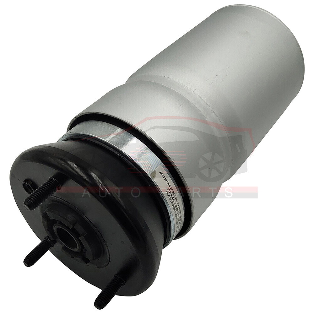
**Replacement part Number**
RNB501580,RNB501180
RNB501220,RNB501250
RNB501480,RNB501610
RPD501480,LR016403
**Package Includes**
Single for Front Left or Right Air Suspension Spring Bag
Removal Guideline:
Caution: Damage to the vehicle and air suspension system can be incurred if work is carried out in a manner other than specified in the instructions or in a different sequence.
To avoid the possibility of short circuits while working with electric components consult your owner's manual on how to disconnect your battery.
Consult your vehicle owner's manual,service manual, or car dealer for the correct jacking points on your vehicle and for additional care, safety and maintenance instructions. Under no circumstances should any work be completed underneath the vehicle if it is not adequately supported, as serious injuries and death can occur.
Once the vehicle has been raised from the ground, put vehicle in neutral, and then back into park to release the tension on the drivetrain.
1.To avoid the possibility of short circuits while working with electric components consult your owner's manual on how to disconnect your battery.
2.Consult your vehicle owner's manual, service manual, or car dealer for the correct jacking points on your vehicle and for additional care, safety and maintenance instructions. Under no circumstances should any work be completed underneath the vehicle if it is not adequately supported, as serious injuries and death can occur.
1.Set steering to straight ahead.
2.Raise vehicle.
3.Remove front wheels.
4.To release the air pressure from the front struts you will need to remove the right side front wheel well liner.
5.With the wheel well liner removed you are able to access the front valve block located on the rear of the wheel well. slowly release the air pressure from the front struts by loosening the yellow and black air hoses. (FIGURE 2)
6.Next, remove the brake hose and abs sensor wire from the retention bracket on the strut.
7.Also remove the sensor wire from the front side of the strut held on with a small plastic clip.
8.Disconnect the sway bar link by removing the nut holding the ball joint to the strut. you may need to hold the ball joint from spinning by placing a wrench on the two flats of the ball joint.
9.Remove the two large bolts that hold the strut to the spindle assembly.
10.With the nuts and bolts removed from the spindle assembly, pull the spindle outward while pushing the strut inward to disengage them.
11.For models equipped with vds, raise the hood to access the air strut's top damper; for models without, skip to step 16.
12.Remove the two (2) bolts holding the damper to the top of the air strut.
13.Remove the damper from the wire.
14.Remove the electrical plug from the top of the shock rod by pressing in on the two (2) sides and pulling up.
15.under the hood are the upper retention fasteners, remove all three being careful not to drop the strut.
16.With the strut removed you can now gain access to its hose connection, remove the fitting to free the assembly.
17.Removal complete.
Installation Guideline:
1.Install the new o-rings and o-ring spacers provided in the kit in the same orientation as removed in step 7.
2.Install the provided bumpstop over the strut shaft in the depicted orientation.
3.Slide the gold washer over the threaded end of the shock. Ensure the perimeter “lip” is facing downward away from the threads.
4.Slide the new air spring assembly over the shock. Make sure to align the plastic alignment pin on the air spring through the hole in the shock’s piston seat. After you have pushed the lower piston’s alignment pin through the shock’s spring plate, slide the external locking clip over the plastic pin to secure the air spring to the shock.
5.Push the upper black rubber mount over the shock’s shaft. Make sure to place the rubber seal in the correct orientation as depicted on page 11.
6.Slide the black washer over the treaded end of the shock. Ensure the perimeter “lip” is facing upward and towards the nut.
7.Thread the M16Nylon lock nut over the strut’s threaded shaft. You can tighten the nut using an impact wrench.
8.Install completed strut back into the vehicle in the reverse order of removal.
**Note**
Please inspect this part carefully prior to installation and contact us with any questions before attempting to install it.
**Questions Before Purchase**
If you have a question about a part you should contact us before buying. Is proud to offer you the best price and fastest service for all your aftermarket parts needs.
| Item Specifics | |
|---|---|
| Placement on Vehicle | Front |
| Type | Air Suspension Strut |
| Fitment Type | Direct Replacement |
| Size | Single Dimension(CM) 37.5(Length)*15(Width)*15(Height) |
| Single Weight(KG) | 4.7 |
| Maximum Operating Pressure (psi) | 160 |
| Minimum Operating Pressure (psi) | 90 |
| Package | Box |
| Modified Item | No |
| Included Hardware | None |
| Drive Layout | Front Engine 4WD |
| Platform | LR3/LR4(L319) |
| Custom Bundle | No |
| Material | Iron Aluminium Alloy Rubber |
| Quantity | 1 PC |
| Manufacturer Warranty | 2 Years |
| OE Spec or Performance/Custom | OE Spec |
| Adjustable | Yes |
| Features | Sealed |
| Brand | Sport-autoparts |
| Manufacturer Part Number | SP11580001AP |
| Interchange Part Number | RNB501580,RNB501180,RNB501220,RNB501610A |
| Other Part Number | RNB501250,RNB501480,RNB501610 |
| Superseded Part Number | RPD501480 LR016403 |
| Return Policy | 30 Days Free Return Or Exchange |
| Surface Finish | High Quality |
We stand behind every product we sell.
All of our brand new items come with a 30-Day money-back or exchange guarantee.
We treat each buyer with a sincere heart, I believe our sincere service , excellent quality of goods will win your trust and support, you may contact us via message and we will reply to you within 24 hours from Monday to Saturday.(Excluding local holidays)
Front Air Suspension Spring Bag For Land Rover LR3/4 Discovery Range Rover Sport
**Fitment** Range Rover Sport
**Replacement part Number** RNB501580,RNB501180
**Package Includes**
Removal Guideline: Caution: Damage to the vehicle and air suspension system can be incurred if work is carried out in a manner other than specified in the instructions or in a different sequence. To avoid the possibility of short circuits while working with electric components consult your owner's manual on how to disconnect your battery. Consult your vehicle owner's manual,service manual, or car dealer for the correct jacking points on your vehicle and for additional care, safety and maintenance instructions. Under no circumstances should any work be completed underneath the vehicle if it is not adequately supported, as serious injuries and death can occur. Once the vehicle has been raised from the ground, put vehicle in neutral, and then back into park to release the tension on the drivetrain. 1.To avoid the possibility of short circuits while working with electric components consult your owner's manual on how to disconnect your battery. 1.Set steering to straight ahead. 2.Raise vehicle. 3.Remove front wheels. 4.To release the air pressure from the front struts you will need to remove the right side front wheel well liner. 5.With the wheel well liner removed you are able to access the front valve block located on the rear of the wheel well. slowly release the air pressure from the front struts by loosening the yellow and black air hoses. (FIGURE 2) 6.Next, remove the brake hose and abs sensor wire from the retention bracket on the strut. 7.Also remove the sensor wire from the front side of the strut held on with a small plastic clip. 8.Disconnect the sway bar link by removing the nut holding the ball joint to the strut. you may need to hold the ball joint from spinning by placing a wrench on the two flats of the ball joint. 9.Remove the two large bolts that hold the strut to the spindle assembly. 10.With the nuts and bolts removed from the spindle assembly, pull the spindle outward while pushing the strut inward to disengage them. 11.For models equipped with vds, raise the hood to access the air strut's top damper; for models without, skip to step 16. 12.Remove the two (2) bolts holding the damper to the top of the air strut. 13.Remove the damper from the wire. 14.Remove the electrical plug from the top of the shock rod by pressing in on the two (2) sides and pulling up. 15.under the hood are the upper retention fasteners, remove all three being careful not to drop the strut. 16.With the strut removed you can now gain access to its hose connection, remove the fitting to free the assembly. 17.Removal complete.
Installation Guideline: 1.Install the new o-rings and o-ring spacers provided in the kit in the same orientation as removed in step 7. 2.Install the provided bumpstop over the strut shaft in the depicted orientation. 3.Slide the gold washer over the threaded end of the shock. Ensure the perimeter “lip” is facing downward away from the threads. 4.Slide the new air spring assembly over the shock. Make sure to align the plastic alignment pin on the air spring through the hole in the shock’s piston seat. After you have pushed the lower piston’s alignment pin through the shock’s spring plate, slide the external locking clip over the plastic pin to secure the air spring to the shock. 5.Push the upper black rubber mount over the shock’s shaft. Make sure to place the rubber seal in the correct orientation as depicted on page 11. 6.Slide the black washer over the treaded end of the shock. Ensure the perimeter “lip” is facing upward and towards the nut. 7.Thread the M16Nylon lock nut over the strut’s threaded shaft. You can tighten the nut using an impact wrench. 8.Install completed strut back into the vehicle in the reverse order of removal.
**Note**
Please inspect this part carefully prior to installation and contact us with any questions before attempting to install it.
**Questions Before Purchase** If you have a question about a part you should contact us before buying. Is proud to offer you the best price and fastest service for all your aftermarket parts needs. 1.The note there will NOT be read. If you want to change the shipping address, please contact us by eBay messages.
2.(if you want cancel orders or change address pls contact us within 6 hours after payment,or we are not responsible for shipping a replacement.)
3.Payment must be received within 10 days as auction ended or order might be delayed.
We treat each buyer with a sincere heart, I believe our sincere service , excellent quality of goods will win your trust and support, you may contact us via message and we will reply to you within 24 hours from Monday to Saturday.(Excluding local holidays) 1. We maintain high standards of excellence (five stars review)and strive for 100% customer satisfaction! FEEDBACK IS VERY IMPORTANT TO US. We request that you contact us immediately BEFORE you give us neutral or negative feedback, so that we can satisfactorily address your concerns.
2. It is impossible to address issues if we do not know about them!
All rights reserved. |
Shop Category Hot Item
Excellent Delivery
Help & Info Payment Policy Shipping Policy Return Policy FAQ About Us |