



|
|
|

|

|

|

|

|

|

|

|

|

|

|
Vehicle Compatibility Information
For Honda Odyssey 2005-2010 V6 3.5L Petrol Front Right
For Honda Ridgeline 2006-2014 V6 3.5L Petrol Front Right
What Are The Signs Of a Failing CV Axle?
You may notice a clicking sound when turning the wheel or accelerating and feel a vibration as the vehicle is in motion. You may also notice grease on the inside of your wheels or tires as the lubricant leaks out from a damaged CV boot.
The steps and tools needed for an CV axle replacement
This is a challenging and technical project
Tool List
Jack
Jack stands
Automotive tool set (pliers, screwdrivers, sockets)
Pry bar
Lubricant
Brake Cleaner
Hammer or mallet
Impact wrench (optional)
CV axle replacement
Pro Tip
Additional specialized tools such as tie-rod end pullers, ball joint removers, and vehicle-specific sockets may be required
1. Slightly loosen the wheel lug nuts. Raise and secure the vehicle. Remove the wheels. Remove the cotter pin. Unlock the spindle nut safety fastener according to the repair manual instructions.
Tip: Leave one side assembled while you work on the other so you can remember how things go back together.
2. Loosen the nut with a proper socket and breaker bar. Another bar or large screwdriver wedged between the lug nuts can help hold the wheel in place. Brake application simplifies the wheel turn issue.
3. On some vehicles, the brake caliper and rotor must be removed before proceeding. Refer to your repair manual for your vehicle's requirements. If you find yourself having to remove the brake caliper, suspend it from a point on the fFor Rame or wheel well with a length of coat hanger wire so it doesn't hang from its brake hose.
4. Remove the cotter pin and castle nut from the lower ball-joint. Disconnect the ball-joint from the steering knuckle with a removal tool (your pickle fork is likely to come in handy here). Swing the knuckle and hub outward to free the outboard axle assembly.
5. Gently wedge a pry bar or a large flat blade screwdriver between the axle and transmission. Carefully pry the axle assembly away from the transmission. Be careful not to damage any transmission seals.
6. The drive axle assembly should now slide right out. Take a good look at the drive assembly location, and then remove. The new one will go back the same way.
7. Grease the splines before insertion with gear grease. Insert the replacement drive axle assembly and reverse the disassembly process. Torque all fasteners to specification. Don't forget to use new cotter pins.
Noticed
-Instruction is not included. Professional installation is recommended
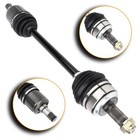
-Accessories: You will get exactly showing in the picture
-Please confirm your original part number before purchasing
-Please Send us a message for anything we can help you with
| Item Specifics | |
|---|---|
| Manufacturer Part Number | X10389101B |
| Brand | X-EngineClub |
| Placement on Vehicle | Front Right |
| Fitment Type | Direct Replacement |
| Part Type | CV Axle Assembly,CV Axle Shaft |
| Quantity | 1 |
| Surface Finish | Heat treatment |
| Non-Domestic Product | No |
| OE/OEM Part Number | 44305SHJA01,44305SHJC01,447-50350R |
| Superseded Part Number | 44305SJCA01,44305SJCA11 |
| Interchange Part Number | 60-4225,60-4259,66-4225 |
| Mounting Hardware Included | No |
| Length | 26 3/4" |
| Colour | Normal black |
| Bundle Listing | No |
| Manufacturer Warranty | 1 Year |
| Main composition | steel |
| OE Spec or Performance/Custom | Performance/Custom |
| Modified Item | No |
| Input Shaft Connection Style | Splined |
| Input Shaft Spline Count | 27 |
| Output Shaft Connection Style | Spline |
| Drive Type | FWD |
| Transmission Type | Automatic |
| ABS Ring Included | No |
| Axle Nut Locking Type | Stake |
| Spindle Nut Included | Yes |
| Spindle Nut Thread Size | M26X1.5 |
1.Payment by eBay approved method.
2.(if you want cancel orders or change address pls contact us within 6 hours after payment,or we are not responsible for shipping a replacement.)
3.Payment must be received within 10 days as auction ended or order might be delayed.
1. Orders processed within 24 hours of payment verification.
2. The images shown are not the actual item and are for your reference only.
3. If you have not received your shipment within 15 days from payment , please contact us. We will track the shipment and get back to you as soon as possible with a reply. Our goal is customer satisfaction!
1. You have 30 days to contact us and 10 days to return it from the date it was received.
2. All returned items must be in the original packaging and you must provide us with the shipping tracking number, specific reason for the return, and item custom lable.
3. We will refund your full winning bid amount, upon receipt of the item in its original condition and packaging with all components and accessories included, AFTER both Buyer and Seller cancel the transaction from eBay. OR, you may choose to have a replacement.
You may contact us via message if you have any questions and we will reply to you within 24 hours from Monday to Saturday.(Excluding local holidays)
Shop Category Hot Item
New List Item
Help & Info Payment Policy Shipping Policy Return Policy FAQ About Us default 10 |
CV Axle Assembly For 2010-2005 Honda Odyssey V6 3.5L Petrol Front Passenger
Vehicle Compatibility Information For Honda Odyssey 2005-2010 V6 3.5L Petrol Front Right
What Are The Signs Of a Failing CV Axle? You may notice a clicking sound when turning the wheel or accelerating and feel a vibration as the vehicle is in motion. You may also notice grease on the inside of your wheels or tires as the lubricant leaks out from a damaged CV boot.
The steps and tools needed for an CV axle replacement This is a challenging and technical project Tool List Jack Jack stands Automotive tool set (pliers, screwdrivers, sockets) Pry bar Lubricant Brake Cleaner Hammer or mallet Impact wrench (optional) CV axle replacement Pro Tip 1. Slightly loosen the wheel lug nuts. Raise and secure the vehicle. Remove the wheels. Remove the cotter pin. Unlock the spindle nut safety fastener according to the repair manual instructions. Tip: Leave one side assembled while you work on the other so you can remember how things go back together. 2. Loosen the nut with a proper socket and breaker bar. Another bar or large screwdriver wedged between the lug nuts can help hold the wheel in place. Brake application simplifies the wheel turn issue. 3. On some vehicles, the brake caliper and rotor must be removed before proceeding. Refer to your repair manual for your vehicle's requirements. If you find yourself having to remove the brake caliper, suspend it from a point on the fFor Rame or wheel well with a length of coat hanger wire so it doesn't hang from its brake hose. 4. Remove the cotter pin and castle nut from the lower ball-joint. Disconnect the ball-joint from the steering knuckle with a removal tool (your pickle fork is likely to come in handy here). Swing the knuckle and hub outward to free the outboard axle assembly. 5. Gently wedge a pry bar or a large flat blade screwdriver between the axle and transmission. Carefully pry the axle assembly away from the transmission. Be careful not to damage any transmission seals. 6. The drive axle assembly should now slide right out. Take a good look at the drive assembly location, and then remove. The new one will go back the same way. 7. Grease the splines before insertion with gear grease. Insert the replacement drive axle assembly and reverse the disassembly process. Torque all fasteners to specification. Don't forget to use new cotter pins.
Noticed -Instruction is not included. Professional installation is recommended -Accessories: You will get exactly showing in the picture -Please confirm your original part number before purchasing -Please Send us a message for anything we can help you with
1.Payment by eBay approved method. 2.(if you want cancel orders or change address pls contact us within 6 hours after payment,or we are not responsible for shipping a replacement.) 3.Payment must be received within 10 days as auction ended or order might be delayed. 1. Orders processed within 24 hours of payment verification. 2. The images shown are not the actual item and are for your reference only. 3. If you have not received your shipment within 15 days from payment , please contact us. We will track the shipment and get back to you as soon as possible with a reply. Our goal is customer satisfaction! 1. You have 30 days to contact us and 10 days to return it from the date it was received. 2. All returned items must be in the original packaging and you must provide us with the shipping tracking number, specific reason for the return, and item custom lable. 3. We will refund your full winning bid amount, upon receipt of the item in its original condition and packaging with all components and accessories included, AFTER both Buyer and Seller cancel the transaction from eBay. OR, you may choose to have a replacement. You may contact us via message if you have any questions and we will reply to you within 24 hours from Monday to Saturday.(Excluding local holidays) All rights reserved. |
|||||||||||||||||||||||||||||||||||||||||||||||||||||||||||||||||||||||||||||||||||||||||||||||||||||||||||||||||